Guide to Suspension Geometry Part 2
Daily Slideshow: In part two we look at the more dynamic side of suspension movement.
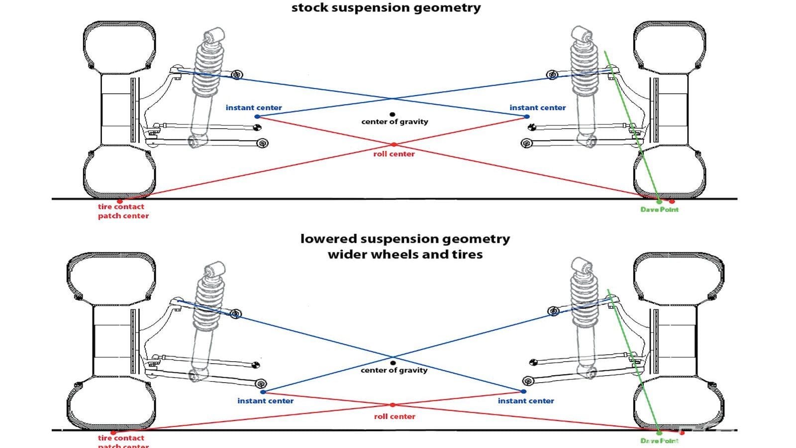


Roll Centers
Roll centers are an imaginary point where upper and lower control arms intersect in relation to the center line of a tire’s contact patch. There is one at the front of the car (front roll center) and one at the rear of the car (rear roll center). As your car leans, the center of gravity and roll center works like a fulcrum to resist roll. Put them closer together and you get less roll, farther away and you get more roll. And, because there are a front roll center and rear roll center you can change which end has more grip. It is also why slamming your car without making the proper adjustments can be very detrimental to your vehicles handling. It’s all about retaining proper angles.
Anti-Dive / Anti-Squat Geometry
When a driver presses the brake pedal firmly the nose of the race car drops down and the rear of the race car lifts up. This change in pitch can be counteracted be moving the top upper ball joint behind the lower ball joint when viewed from the side profile. At the rear, the opposite is done and is called anti-squat geometry. On vehicles that rely heavily on air flow for proper aerodynamics, this becomes a vital part of the design equation as it can help to maintain a fixed ride height under braking and accelerating. All of this results in a more consistent and predictable machine which allows the driver to push with confidence.
>>Join the conversation about part 2 of this suspension geometry guide right here in Rennlist.com.
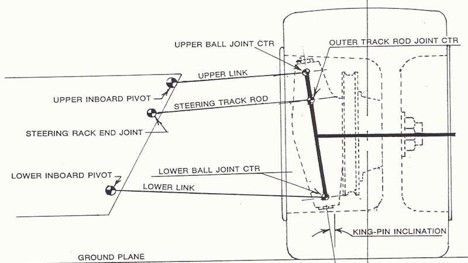
Bump Steer & Ball Joints
Without a doubt one of the nastiest conditions you can experience—especially at high speed—bump steer is exactly what it sounds like: you go over a bump and the car changes direction without you giving any input to the steering wheel. Sounds like fun when you’re flat out through one of the fastest corners on, say, the Nurburgring, right? To eliminate bump steer, a designer will try as much as possible to ensure that the upper control arms ball joints, steering arms, and lower control arm ball joints all align with each other when viewed from the front of the vehicle in a vertical plane. By keeping these three points traveling on the same arc you avoid any unexpected changes in toe angle.
>>Join the conversation about part 2 of this suspension geometry guide right here in Rennlist.com.
Upper Control Arm Length
Length of the upper control arms can be shortened which can have negative effects in extreme situations. Remembering that a car’s mass is connected to the control arms and that as a wheel moves up in travel it gains negative camber? Well, shortening to upper arm to an unrealistic length can actually cause your car to gain excessive camber under braking which results in a traction loss and therefore instability. A driver of this machine might have no traction going into a braking zone and end up in the gravel lap after lap.
>>Join the conversation about part 2 of this suspension geometry guide right here in Rennlist.com.
Combining Everything
Now that we have a fundamental understanding of suspension geometry, how does it all work together? Where are compromises made and what else is there to learn? Well, the short answer is a lot, but we’ll cover some of these trade-offs in the final chapter of suspension geometry. From turn in to corner exit, you’ll understand everything there is to know in order to have a full grasp of what’s going on underneath your right foot. Hope you enjoyed reading. See you next time.
>>Join the conversation about part 2 of this suspension geometry guide right here in Rennlist.com.
For help with your maintenance and repair projects, please visit our How-to section in the forum.