The Throttle Position Switch on the 928 can be a pain to access if it fails. Upon diagnosis of a bad TPS, use this step-by-step guide of removing your intake system to replace that pesky little part.
By Joseph Coelho - April 13, 2015
Contributors: Dave Chamberland, Dwayne
This article applies to the Porsche 928 (1979-1995).
The Porsche 928 utilizes a Throttle Position Switch (TPS) to switch ignition mapping depending on throttle input. While newer cars use a potentiometer to measure every position of the throttle opening, the 928's TPS simply signals to the ECU whether the throttle is nearly closed or opened over 3/4 of the way, so that corrections to fueling and ignition timing can be made. Unfortunately, this TPS is prone to failure and becomes unable to properly signal the throttle load request back to the ECU which can cause various poor running conditions. What is even more unfortunate is that the TPS is buried under the intake manifold and involves a lengthy repair and replace procedure. However, if you are going to replace the TPS, it is an opportune time to tend to other components that also require the removal of the intake.
Materials Needed
8, 10, 13, 19, & 22mm sockets
3 & 6 inch extension
1/4" or 3/8" ratchet
Wobble adapter
15, 17, 19, & 24mm open-ended or flare-nut wrenches
4, 5, 6, 8mm allen wrenches
Phillips screwdriver or 7mm nut driver
Needles nose pliers
Shop rags/plastic bags
Catch pan
Bosch two-pole electrical connector tool
WD-40 or Silicon Spray
The following procedure is for the 1987+ 928 models with the LH-Jetronic Injection system. Gaining access to the TPS on pre-1987 cars is a bit easier, and sometimes can be done with only partial disassembly of the intake system.
Step 1 – Access fuel delivery system
The first step toward removing the intake manifold to reach the TPS involves removing a handful of components to reach the fuel delivery system. Make sure the car is in a place that it can sit for a period of time without being disturbed as many parts and small pieces will be removed.
Remove engine compartment crossmember.
Remove intake tubes. They should slide off with a firm tug.
Remove airbox assembly: Undue airbox clips, slide out the airbox cover and air filter, then remove the two nuts securing the air box housing to its support brackets. The airbox is attached to the mass airflow sensor (MAF) with a snug fit. Once the airbox is slid off, cover the MAF with a shop rag or plastic baggie.
Remove breather hose connected to the left and right cam covers (For GTS models only).
Figure 1. 928 engine compartment.
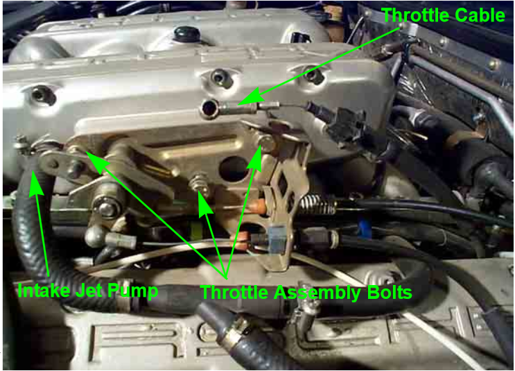
Disconnect Intake Jet line.
Disconnect throttle plate cable guide from throttle plate assembly by depressing the small plastic tabs on each side and wiggling the guide out. Do not undo the throttle cables or else throttle readjustment will be necessary upon reassembly.
With cable guide removed, remove the three bolts securing the throttle plate assembly.
Figure 2. 928 throttle plate and cable assembly.
Remove the fuel rail covers. Each fuel rail is secured by two bolts.
Disconnect fuel rails using two flare nut wrenches (15mm & 19mm) to prevent rounding off the fuel line fittings. Have shop rags or catch pan ready to catch emerging fuel.
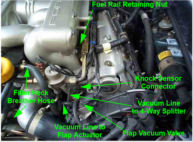
Disconnect vacuum line for the intake flap.
Disconnect electrical plug for intake flap actuator.
Figure 3. Fuel rail, electrical connections, and vacuum lines.
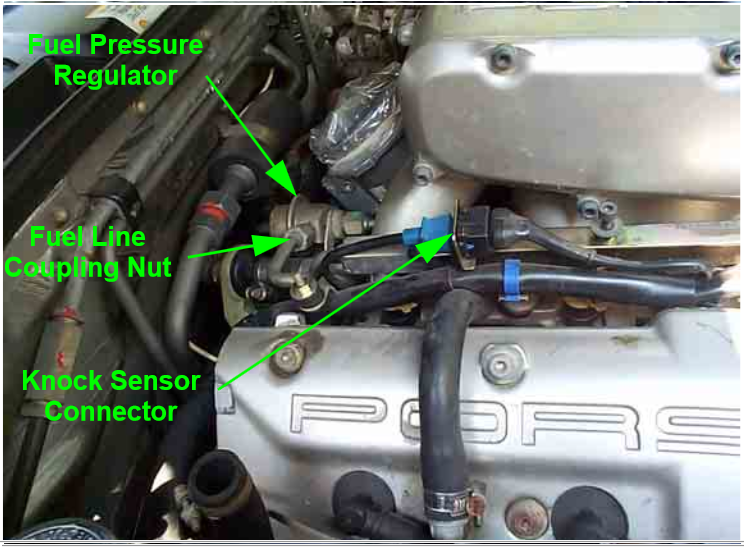
Unplug both driver side and passenger side knock control sensors.
Disconnect fuel fittings at fuel pressure regulator.
Figure 4. Fuel pressure regulator and passenger knock sensor plug.
Pro Tip
Be sure the car is not moved or lifted after the engine compartment crossmember has been removed as the increased chassis flex could cause the windshield to crack.
Step 2 – Remove fuel rails and fuel injectors
Removal of the fuel rails and fuel injectors can be quite difficult as the injectors have typically been in place for many years and can easily be damaged. Proper lubrication and a bit of patience will go a long way during the following steps.
Remove the Fuel Rail hold down nuts (two per rail).
Remove fuel rail wiring harness hold down clips.
Disconnect electrical plug at each injector (Bosch two-pole electrical connector tool recommended, but not required, for removal).
Figure 5. Fuel injector harness and plugs.
Remove three-way hose at oil filler neck.
Figure 6. Oil filler hoses.
Disconnect fuel pressure damper fuel lines with a 24mm and 19mm wrench.
Remove fuel pressure damper hold-down bolt with 6mm Allen wrench and remove damper.
Figure 7. Fuel pressure damper.
The fuel rails and injectors are now ready for removal. Use of WD-40 or Silicon Spray is recommended to lubricate and free stuck injectors.
The injector rails and injectors can be removed as a complete assembly by gently working them of out the intake. Be patient as the injectors can easily be damaged. You can also unclip the injectors from the fuel rails and remove each individual injector separate of the fuel rail.
Figure 8. Fuel rail removal.
Step 3 – Remove remaining hoses, lines, and connections
If you have made it this far, keep up the good work! However, a few more components must first be removed before the removal of the intake manifold can take place.
Disconnect passenger cam cover breather hoses and reroute over injector wiring harness (Not applicable to GTS models).
Disconnect vacuum lines from air pump diverter valve and fuel tank vent diaphragm. Reroute over wiring harness.
Figure 9. Rerouting of hoses and lines.
Loosen hose leading to brake booster and reroute over injector wiring harness.
Figure 10. Brake booster hose.
Ensure vacuum feed line at rear of manifold is disconnected.
Figure 11. Vacuum feed line.
Remove the fuel pressure regulator and fuel pressure damper mount nuts and bolts (one of each for each device) and remove from car.
Figure 12. Hold down securing fuel pressure regulator.
You can now remove the air intake bolts. There are 10 in total.
Figure 13. Intake bolt removal.
Disconnect Intake temperature sensor on top of intake manifold (see Figure 1 above).
Remove throttle cable from throttle body.
Figure 14. Throttle cable.
Step 4 – Remove intake manifold
With all accessories disconnected and rerouted away from the intake manifold, it can now be separated from the engine. However, there are still several connections underneath the intake that need to be disconnected before the complete intake assembly can be removed from the car.
The intake manifold is securely sealed against the cylinder heads and will take some force to separate the two. If using a pry bar, be sure to place leverage on reinforced areas of the engine.
Figure 15. Intake separation.
With the intake lifted free, disconnect the other end of the three-way hose (from Figure 6) from the intake manifold.
Disconnect TPS plug.
Figure 16. TPS plug.
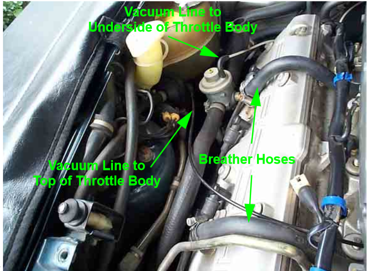
On the passenger side, remove the lower breather hose from the throttle body boot. The hose above is a cam cover breather and does not need to be disconnected for the intake to be removed.
Nearby, directly on the throttle body, is a vacuum line that must also be removed.
Figure 17. Throttle body boot breather hose.
The last plug to be disconnected is the Idle Control Valve. Use a pair of needle nose pliers or similar to separate the connector located under the intake manifold.
Figure 18. Idle control vale plug.
You can now remove the intake assembly by slowly lifting upward. Make sure it does not snag on any hoses, fittings, or electrical wires as you are removing it.
Figure 19. Intake assembly.
Pro Tip
Cover the intake ports on the cylinder heads with shop rags to prevent debris and foreign objects from entering the engine.
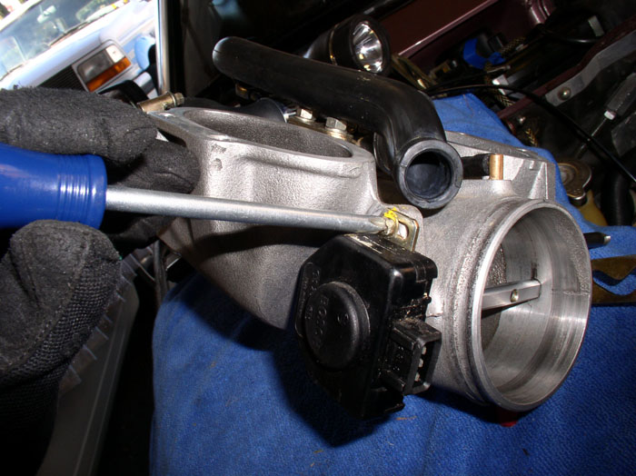
Step 5 – Replace TPS
With the intake assembly removed from the engine, the TPS is now easily accessible. The TPS is mounted to the side of the throttle body. Remove the two Phillips screws securing the TPS to the throttle body and simply pull outward to remove it. Note its orientation so the replacement TPS can be installed "close" to the correct setting. It will make adjustment of the TPS much easier.
Figure 20. TPS removal.
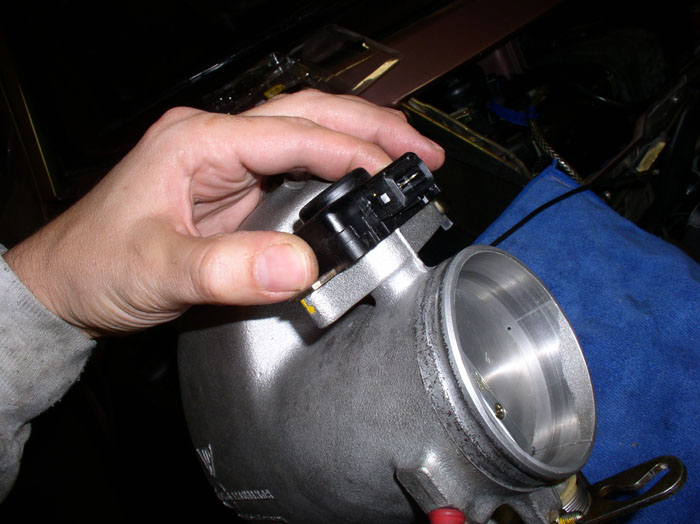
Step 6 – Install new TPS and adjust
The new TPS simply slides over the throttle shaft. Reinstall the TPS in the same orientation as it was removed and lightly snug the two Phillips screws. After the TPS is installed, move the throttle shaft and listen for a click. This click is the contact that controls the idle part of the switch. You want to make sure the click is heard just as the throttle is barely being moved. Most owners suggest the throttle shaft should move approximately 1 degree before contact of the switch is made and the click is heard. Rotate the switch until this setting is achieved before securely tightening the Phillips screws.
Figure 21. Rotate TPS to adjust idle switch setting.
Pro Tip
With the intake assembly removed, it is a good time to replace hard-to-reach parts such as knock sensors, vacuum lines, fuel hoses, the vacuum actuator, intake flap, oil filler, and coolant seals.
Step 7 – Reassembly
With the TPS replaced, along with any gaskets, seals, and any other additional items you that opted to refresh while down here, it is time to reassemble the intake.
Assemble intake components and throttle body.
Plug in all connectors, vacuum lines, and sensors.
Install intake and throttle body onto the manifold, and reinstall throttle cable.
Reinstall additional hard lines and vacuum lines.
Assemble the fuel rails and injectors and refit the rails to the manifold.
Refit additional fueling support items.
Finalize installation of throttle support components.
Reinstall air box, intakes, hoses, and other top-end items.
Double check that everything is fastened correctly, start the car, and listen for vacuum leaks or erratic idle; if everything checks out, then you are done!
Why Is My Car Losing Power?
Giving it gas but going nowhere? Find out why you are losing power.
This article applies to the Porsche 928 (1979-1995).
The Porsche 928, with all of its electronic gadgetry and engine ...
How to Install a Supercharger Kit
Have an itch for more horsepower?
This article applies to the Porsche 993 (1993-1998).
For individuals looking to boost the performance of their Porsche 993, a supercharger kit is ...
Why is My Engine Bucking?
Is your engine experiencing stuttering and a hesitation?
This article applies to the Porsche 928 (1979-1995).
Although the Porsche 928 may have sophisticated gadgets and electronics to ...
How to Cure High Idle
Track down the problem causing your high idle issues.
This article applies to the Porsche 928 (1978-1995).
There are various sources that can cause a high idle issue on Porsche 928 models. ...
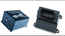
This DIY standalone ECU allows owners the ability to fine tune various engine parameters to increase performance and improve driveability.
4672
1. Megasquirt vs. Microsquirt By today's standards, the engines found ...
Why Does My Car Smell Like Gas?
Have you walked into the garage only to be knocked off your feet by the smell of gas emanating from your Porsche 928?
This article applies to the Porsche 928 (1978-1995).
The ...