Porsche 997: How to Replace Dome Light
Every great Porsche 997 needs a high functioning LED light panel. Read more to learn how you can install yours today.
This article applies to the Porsche 997 (2005-2012).
One of the easiest ways to dress up the interior of your Porsche 997 is with an aftermarket interior light panel. For the 997, it's recommended to go with an LED dome light. The installation process takes about two hours, and LED interior light packages are available for as low as $12 online. The dome light offers convenience and style, and with LED bulbs available in an assortment of colors, you can change the look of your 997 with the change of a single bulb. Let's get started!
Materials Needed
- Soldering iron
- Box cutter
- Pair of pliers
- Soldering cover
- Tape
Step 1 – Locate the first wire
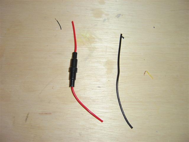
To begin, locate the straight power wire (each end contains a single modular connector). Lay the wire flat on an even surface, and then cut 6 inches from both ends using a pair of pliers. Grab the shorter piece that you just created, and strip it so the black, yellow, green, and red wires are exposed. Next, cut the black and yellow wires. Solder the ends of the green and red wires using a soldering iron.
- The green wire will serve as the positive or "hot" wire.
- The red wire will serve as the negative or "ground" wire.
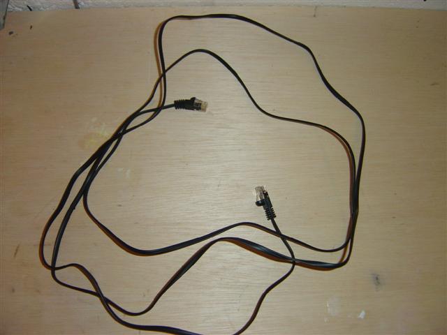
Figure 1. This is a straight power wire. 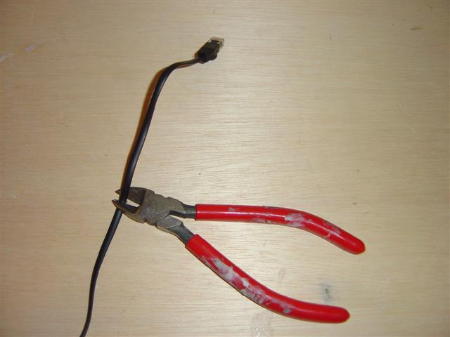
Figure 2. Cut like so. 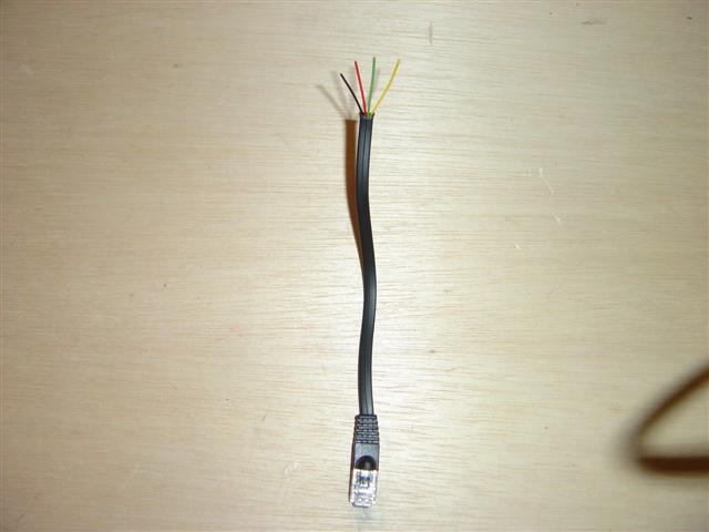
Figure 3. The three wires are exposed.
Step 2 – Locate your direct wire harness
Now that you've located the direct wire harness, measure about three inches from the end (do the same for both sides). Cut the wire accordingly. You will end up with two 3-inch pieces. Now move on to the black wire. For the black wire, you will need to cut 4 inches from each end.
- Finish by stripping both ends of the red and black wires.
- Solder the exposed ends with the soldering iron.
Pro Tip
Apply pressure when cutting the wire for a clean, even slice.
Step 3 – Detach your light assembly
You may feel some resistance, but to remove the light assembly already installed in your 997, you will need to pull the light housing out of the trim. Next, using your bare hands, guide the modular wire that you just prepared in between your vehicle's windshield and the dome light assembly housing.

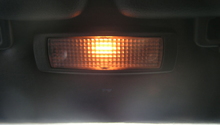
Figure 5. Remove the light housing by pulling down. 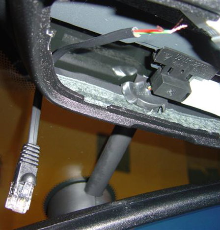
Figure 6. Example of a job well-done.
Pro Tip
The modular plug needs to hang in front of the windshield, and the exposed wires need to sit inside the light assembly housing; adjust the wires as needed.
Step 4 – Preparing vehicle for soldering
With a soldering cloth blanketing the interior of your 997 from ruin, solder one end of the red wire, which has the fuse, to the green wire on the modular wire assembly. Now, solder one end of the black wire to the red wire on the modular wire assembly.
- Wait until the wires cool.
- Tape the joined ends using either heat shrink tubing or electrical tape.
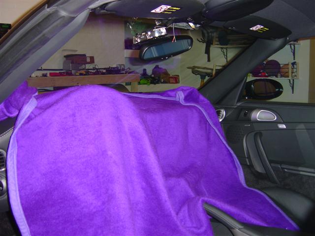
Figure 7. A blanket will also suffice. 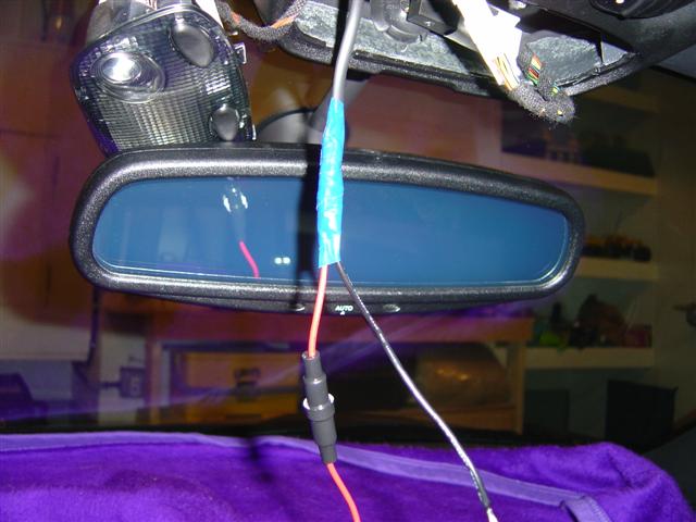
Figure 8. Wrap the entire area.
Pro Tip
It should only take a moment for the wires to cool.
Step 5 – Check the pin numbers on the sockets
Locate the 10 wire harness, which you can find inside the dome light assembly. Using a project knife, remove the black tape, moving slowly as you proceed.
Check the pin numbers on the socket:
- The wire located at pin 2 is switched 12VDC and is black and orange in color.
- The wire at pin 10 is ground and is brown in color.
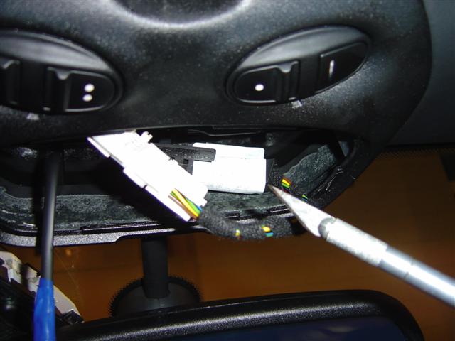
Figure 9. Use a project knife. 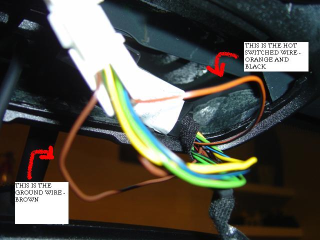
Figure 10. The hot switched wire is orange and black.
Pro Tips
- The ground wire is brown, as shown in Figure 10.
- You will be working with the wires running down the mirror, not the wires extending up into the roof. Don't worry, the colors for the two sets of wires are different. While this information is useful to know, you shouldn't run into any problems confusing the two.
Step 6 – Make the final connections
Cut a quarter of the way down on the wire and then solder the exposed wire.
- The red fuse wire connects to the orange/black wire.
- The other end of the black wire connects to the brown wire.
- Hold each end with tape.
Plug the modular plug into the V1. Turn on the engine for power.
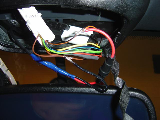
Figure 11. Connected wires. 
Figure 12. Ends held with tape.
Step 7 – Finish up the job
Pack all of the wires neatly back into place in the dome light assembly and replace the dome light. Test your work!
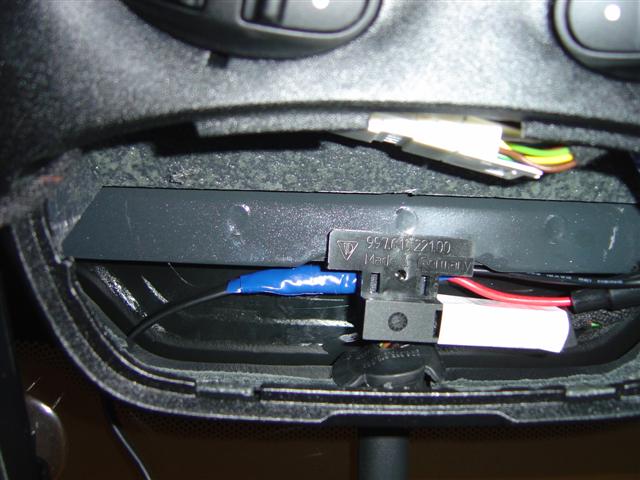
Figure 13. Tidy up. 
Figure 14. Your work here is done!
Related Discussions
- Power Hardwire - Rennlist.com
- Removing Dome Light - Rennlist.com