Porsche 928: How to Rebuild Steering Rack
The Porsche 928 power steering rack has been known to leak. A small drip can quickly turn into a large leak within a very short period of time, damaging the power steering pump if run low on fluid. If your steering rack has developed a leak, give it some attention before the problem progresses.
This article applies to the Porsche 928 (1979-1995).
One of the Porsche 928's Achilles heel is a leaking steering rack. Often times, the outer seals on the rack go bad, and begin to leak fluid into the protective rubber boots. Fluid filled boots combined with the belly pans located underneath the car can mask this problem until the power steering pump begins to moan from a lack of fluid. While most Porsche 928 owners typically suggest installing a re-manufactured steering rack, a leaking unit can often be rebuilt—assuming that all of the hard parts in the rack are in good condition with no excessive wear, pitting, or corrosion. This job, however, is not for the faint of heart as the steering rack is composed of a number of seals, O-rings, bushings, bearings, and washers that must be carefully installed to prevent fluid leaks. In either case, a leaking steering rack must be removed from the car, so why not disassemble it before deciding to rebuild it or replace it?
Materials Needed
- Floor jack and jack stands
- Metric socket set
- Metric wrench set
- Hammer
- Drift punch
- Ratchet and extensions
- Torque wrench
- Blue threadlocker
- Ball joint separating tool (optional)
Step 1 – Remove steering rack
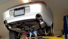
- Lift vehicle and support with jack stands.
(Related Article: How to Jack Up Your Car - Rennlist.com)
- Remove the front wheels.
- Remove the front and rear belly pans. Remove the rear pan first by removing its nine screws (blue arrows in Figure 1) with an 8mm socket. With the screws removed, the pan needs to be slid rearwards for removal. Next, remove nine of the screws (yellow arrows) from the front belly pan with an 8mm socket. The final two screws (red arrows) at the rear of the pan require a 10mm socket.
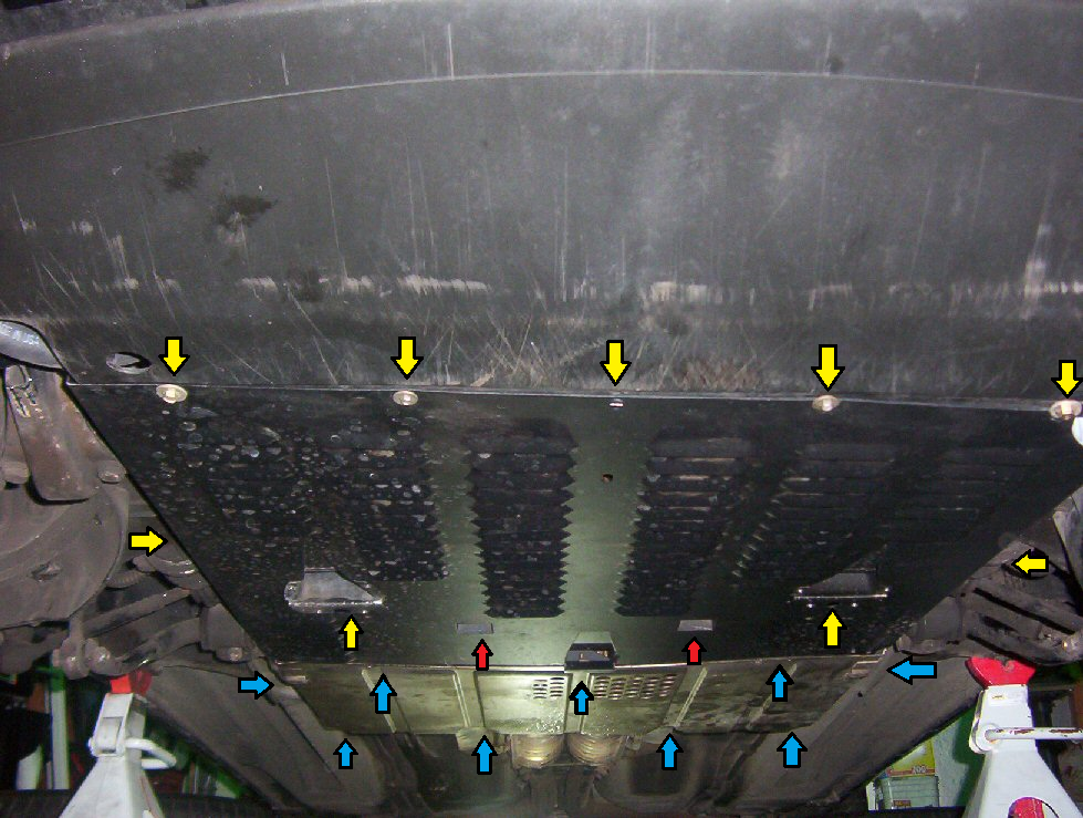
Figure 1. Porsche 928 belly pans. 
Figure 2. Underbody with belly pans removed.
- Loosen the bolts securing the anti-roll bar to the drop links with a 19mm wrench and socket.
- Remove the bolts securing the anti-roll bar to the chassis using a 17mm wrench or socket. Swing the roll bar downwards, and allow to hang. The roll bar can be completely removed if preferred.

Figure 3. Loosening drop links to roll bar. 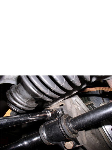
Figure 4. Roll bar to chassis bolt removal. 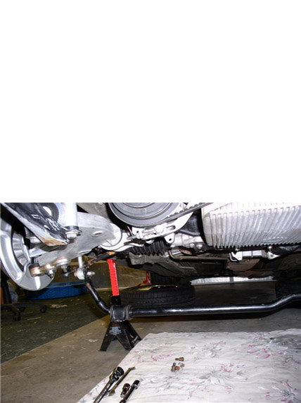
Figure 5. Roll bar loosened and hanging.
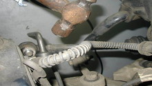
- Remove the tie rods from the rack. The boots will need to be pulled back or cut lengthwise to gain access to the tie rods. Be careful as they may be full of fluid. Use a 22mm (7/8") and 32mm (1-1/4") wrenches to loosen the tie rods. Unscrew the tie rods from the rack. The outer tie rods can instead be removed from the steering knuckle with a ball joint removal tool, and the tie rod assemblies can be removed from the rack once it is out of the car.

- Remove the wiring harness hold-down just in front of the steering rack plate using a 10mm wrench.
- Loosen the (4) 8mm nuts securing the steering rack reinforcement plate to the cross member using a 13mm wrench.

- Remove the bolt on the driver's side of the reinforcement plate using a 17mm wrench.

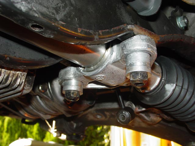
- Remove the (4) 10mm bolts securing the steering rack to the cross member using 17mm wrenches.

- Remove power steering line clamp in driver's side fender with a 10mm wrench.

- The loosened nuts on the steering rack reinforcement plate can now be removed. Removing the plate will reveal the steering rack, which can now be slightly maneuvered to gain access to the final few connections.

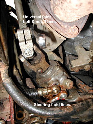
- Remove the nut and bolt on the universal joint at the steering input shaft using a 13mm wrench. Mark its orientation for correct steering wheel alignment during re-installation.
- Remove the fluid lines. Have an oil pan handy to catch emerging fluid.
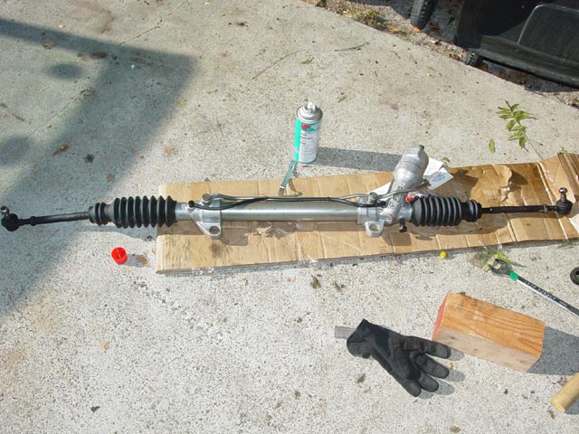
- The steering rack can now be removed from the car, and placed upon a clean work bench to begin disassembly.

Step 2 – Disassemble steering rack
With the rack removed from the car, it is only a matter of disassembling the unit and replacing the seals as well as O-rings. Make sure the steering rack is on a clean work bench before beginning.
- If the tie rods were not removed during Step 1, remove them now.

- Remove the fluid lines and O-rings from the rack (Items 101, 102, 103).
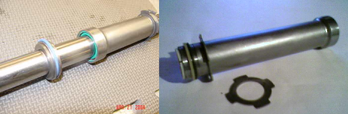
- Remove the locking collars holding the rack together. Use a punch and hammer to loosen the collars. Once broken loose, they will unscrew.
-
Remove the plastic shaft cover (Item 64) at the control tower. Remove three bolts on the tower cover. Carefully remove the tower cover (Item 50), noting the orientation of the seal and O-ring inside.
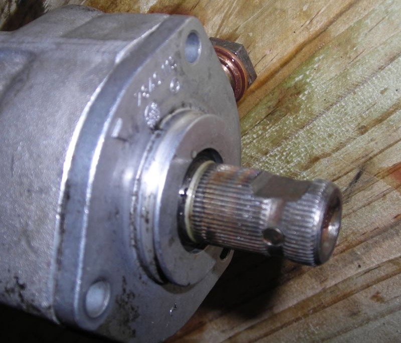
Figure 17. Input shaft control tower cover. 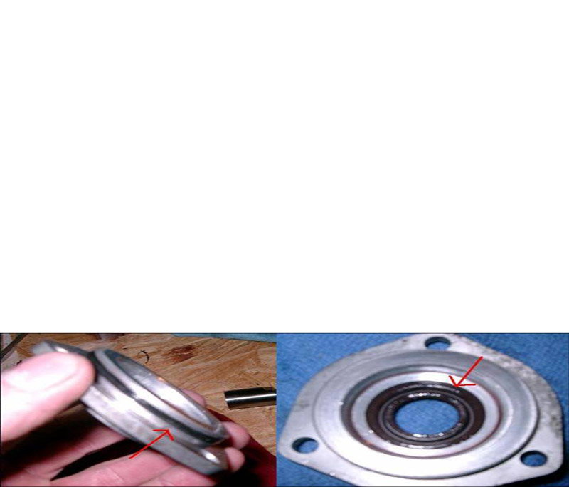
Figure 18. Tower cover seal and O-ring.
- Remove the control valve from the rack housing by pulling on the splined input shaft. You will have to rotate the valve as it is being removed from the housing. Note the orientation of all bearings, seals, O-rings, and washers.
- Under the white nylon rings are rubber O-rings. Replace the nylon rings and O-rings, as well as the seal and O-ring in the control tower cover. A small pick may be useful in removing these O-rings.
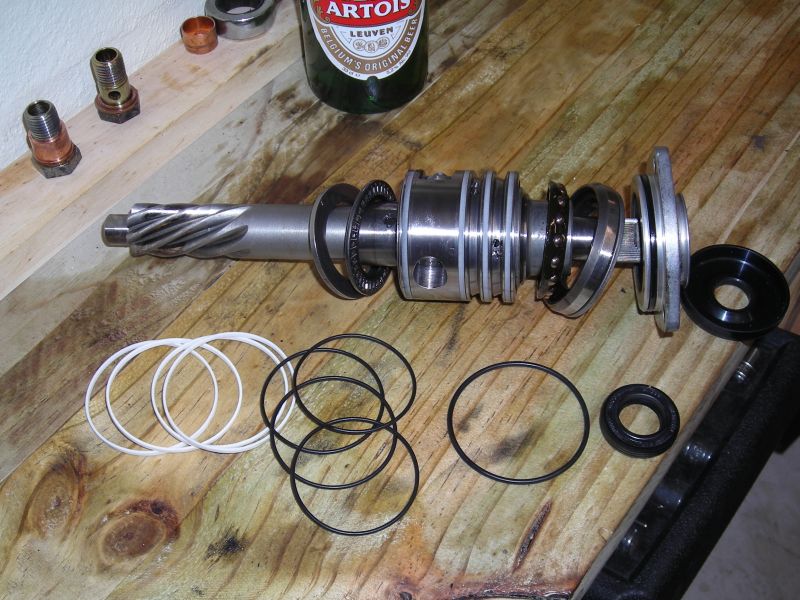
- The rack cylinder can now be separated from the control valve housing and the passenger's side rack end. The steering shaft can also be removed from the control tower housing.
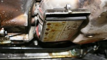
- Remove the two bolts securing the friction pad cover (Item 34) from the backside of the control tower housing. Remove friction pad assembly.

- Replace the O-ring and seal inside of the control tower housing. A blind bearing puller or similar may be needed to remove the seal from the housing. It is extremely important that the housing not be nicked or damaged when removing this seal, or the rack will leak.
- Similarly, replace the seal in the passenger's side rack end. Note that there is a nylon washer behind the seal that needs replacing as well.

Figure 21. Control tower housing seal (O-ring not shown). 
Figure 22. Passenger's side rack end and seals.
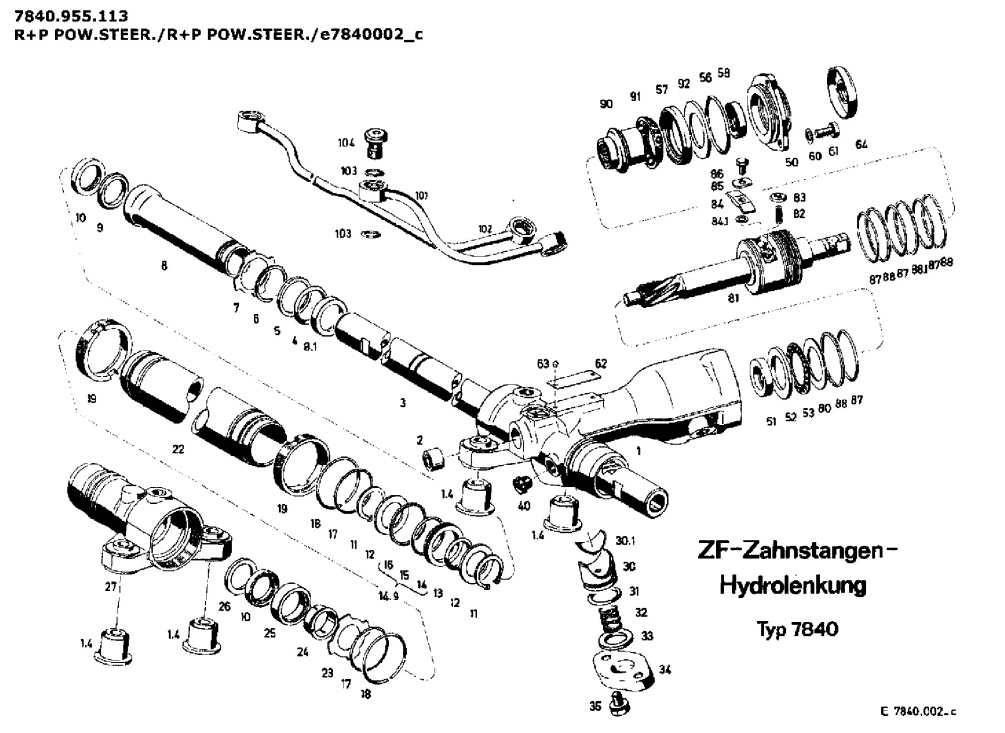
- Remove the shuttle from the steering shaft. This requires removal of snap rings, washers, and a seal. These components are identified in Figure 14 as items 11-16 (note there are two snap rings #11 and two washers #12). Be careful removing the snap rings as the steering shaft cannot be scratched. With these items removed, the shuttle can be slid off of the steering shaft.
-
Replace the seals and O-rings on the steering shaft as well as the shuttle assembly, making sure their orientations are the same as the removed items.

- Replace the O-rings on both ends of the rack cylinder.
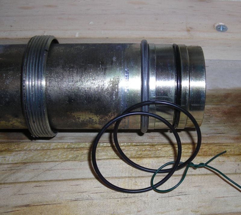
-
Replace rack cylinder seal. Be sure to remove the nylon guide ring before attempting to drive out the old seal. Most seal kits do not include this guide ring, so be careful. Behind the seal is a nylon washer.
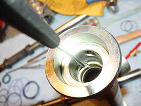
Figure 26. Nylon guide ring removal. 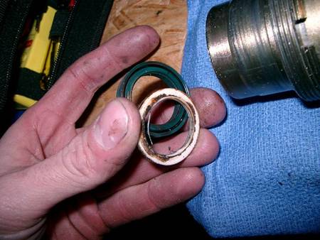
Figure 27. Seal and nylon washer removed.
-
Replaced the nylon friction pad and O-ring.
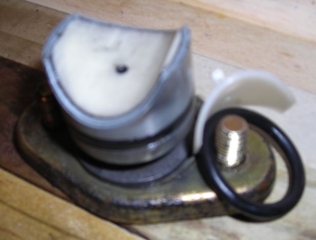
Figure 28. Friction pad and O-ring. - With all seals and O-rings replaced, reassemble the rack in reverse order. It is recommended the seals and O-rings be lubricated with automatic transmission fluid or similar during reassembly.
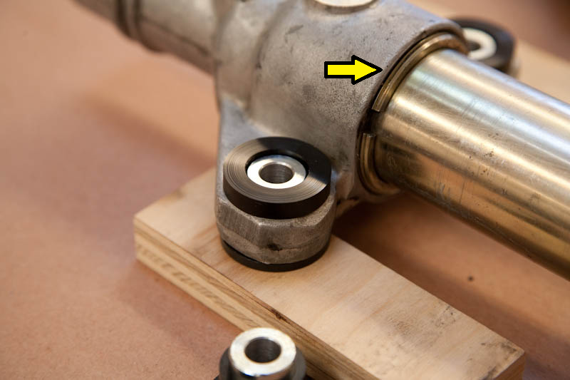
- When assembling the rack cylinder to the control valve housing and passenger's side rack end, be certain the star washers (Items 7 and 23) are pressed firmly against the rack cylinder to ensure the O-rings are properly seated. Press the cylinder into place (on the control valve housing or passenger's side rack end), while watching the star washer through the banjo bolt hole to see that it seats. After tightening the locking ring, the washer should be nearest the hole if properly in place.
- Additionally, stand the rack in the upright position when installing the control valve into its housing to ensure it is centered. After installation, turn the shaft to make sure it does not bind. If binding occurs, remove and re-install the control valve.
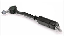
- The tie rods and dust boots can be installed with the rack on the bench. The torque specification for the tie rods are 110 ft-lbs, so give them a good pull. It is recommended blue threadlocker be applied to the tie rods.
Pro Tip
With the rack disassembled, inspect for any wear, pitting, corrosion, or nicks in the rack components. If any components are damaged, it is highly recommended that the steering rack be replaced with a re-manufactured unit, as it will most likely continue to leak even though new seals have been installed.
Step 3 – Test steering rack for leaks
The rack can be tested for leaks without completely installing it back in the vehicle.
- Place the rack back in the car with the (4) 10mm mounting bolts finger tight.
- Connect the universal joint to the splined input shaft on the rack.
- Re-install the fluid lines using new copper crush washers and tightening to 22 ft-lbs.
- Leave the remainder of the components disconnected.
- Fill the power steering fluid reservoir.
- Start the car. Then, turn the steering wheel back and forth. Do not excessively turn the steering wheel to full lock as the tie rods are disconnected and the steering stop can be exceeded. Add to the power steering reservoir as needed.
- The full rack is visible, and can now be inspected for leaks.
- If no leaks are found, torque the rack mounting bolts to 34 ft-lbs.
- Re-install the steering rack reinforcement plate and torque to 21 ft-lbs
- Re-install power steering line clamp and wiring harness strap.
- If the outer tie rods were removed from the steering knuckle, re-install and torque to 48 ft-lbs,
- Reattach anti-roll bar to chassis and torque to 50 ft-lbs. Tighten roll bar to drop link fasteners to 63 ft-lbs.
- Re-install belly pans and wheels.
Related Discussions
- Steering Rack Seals and O-Ring Pics - Rennlist.com
- Steering Rack Play - Rennlist.com
- Steering Rack Question - Rennlist.com
- 928 Steering Rack Repair Kit - Rennlist.com